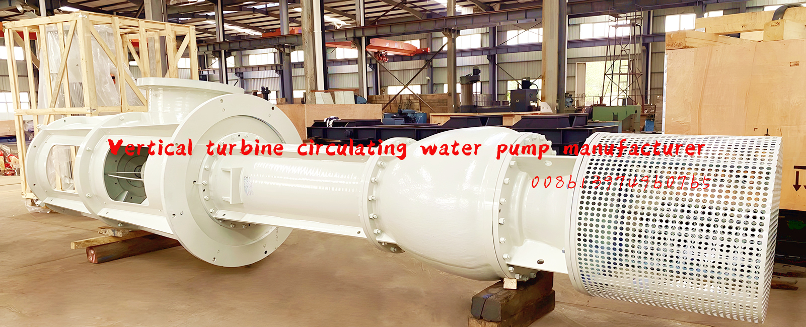
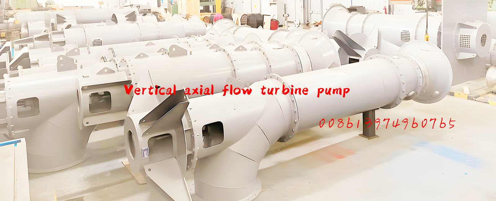
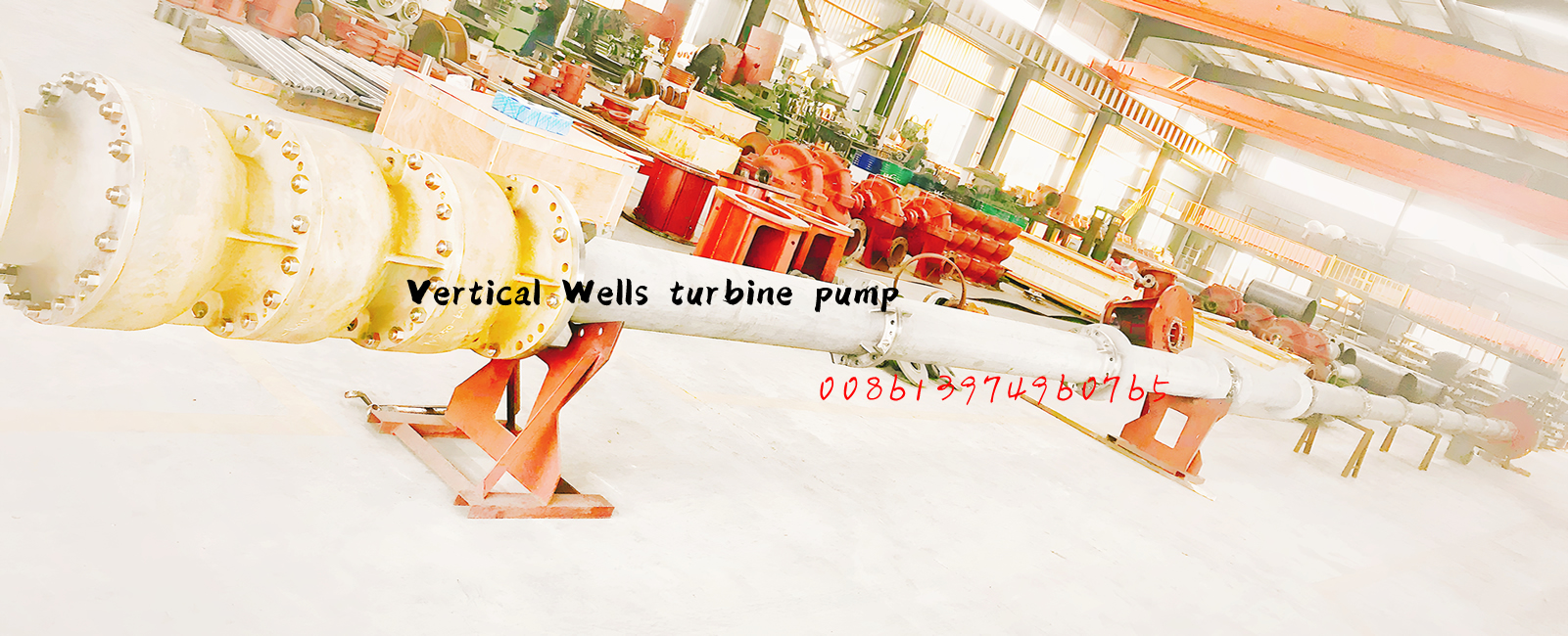
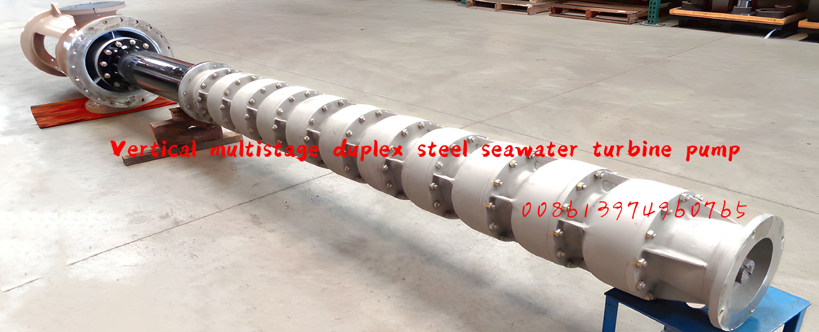
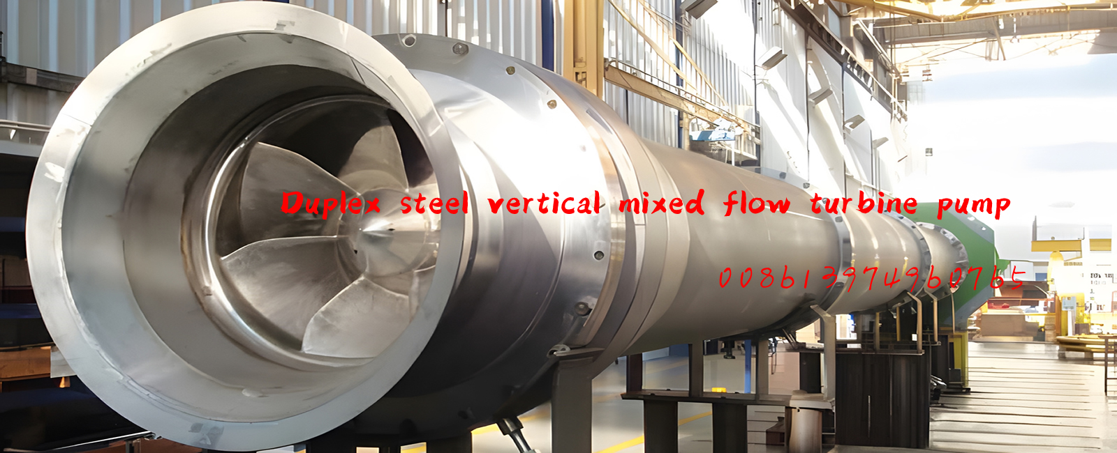
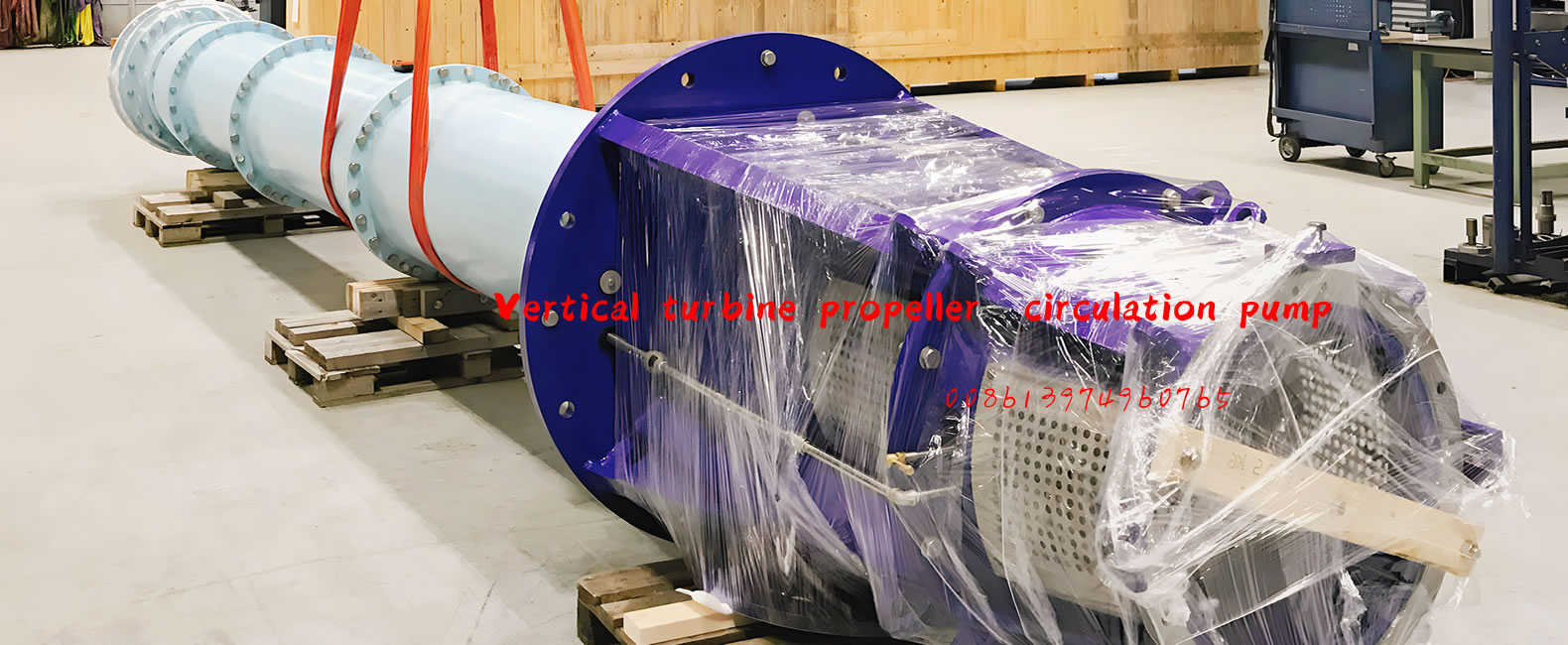
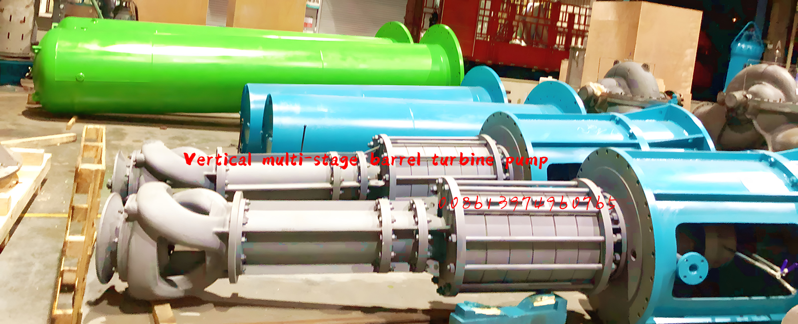
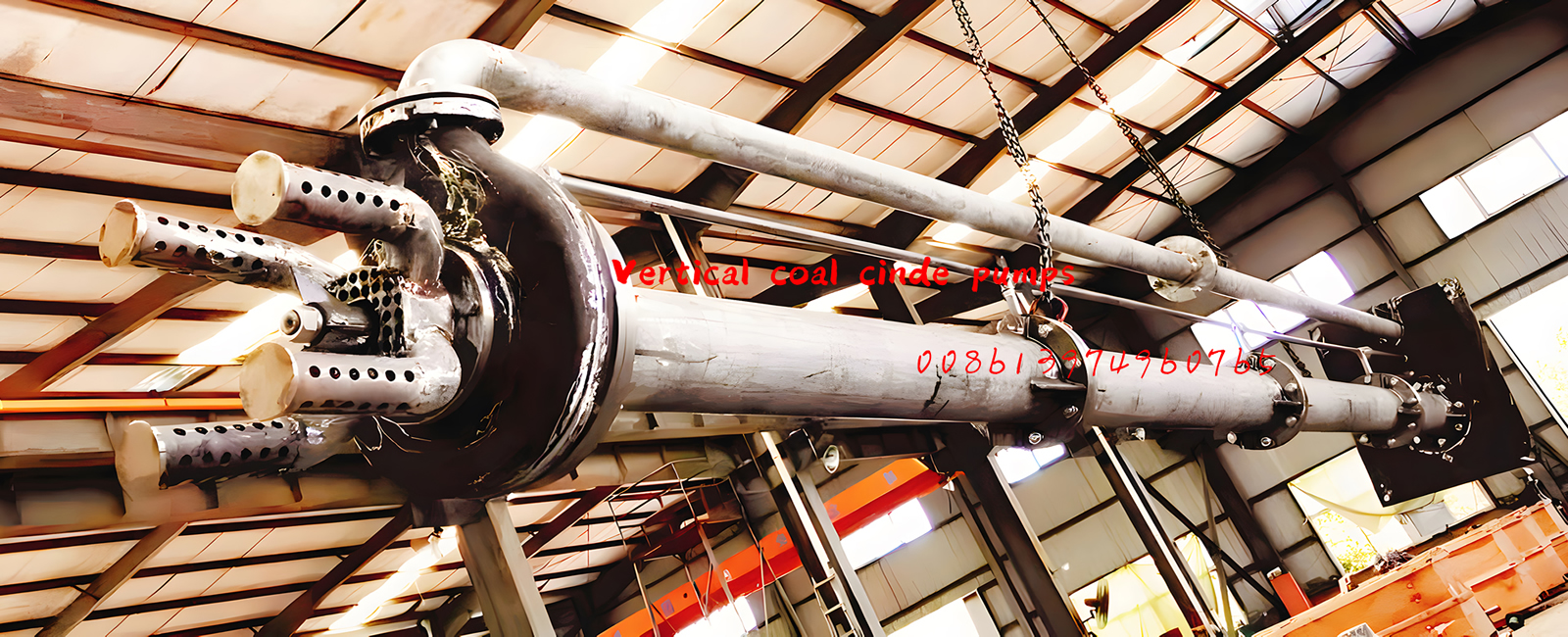
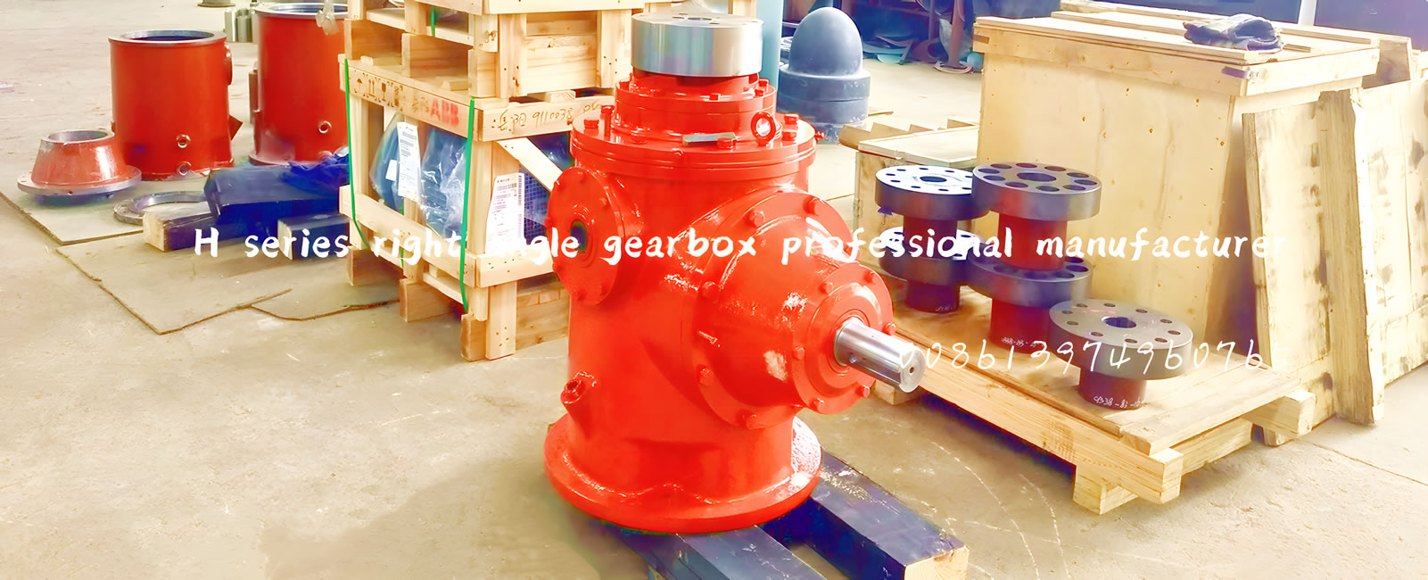
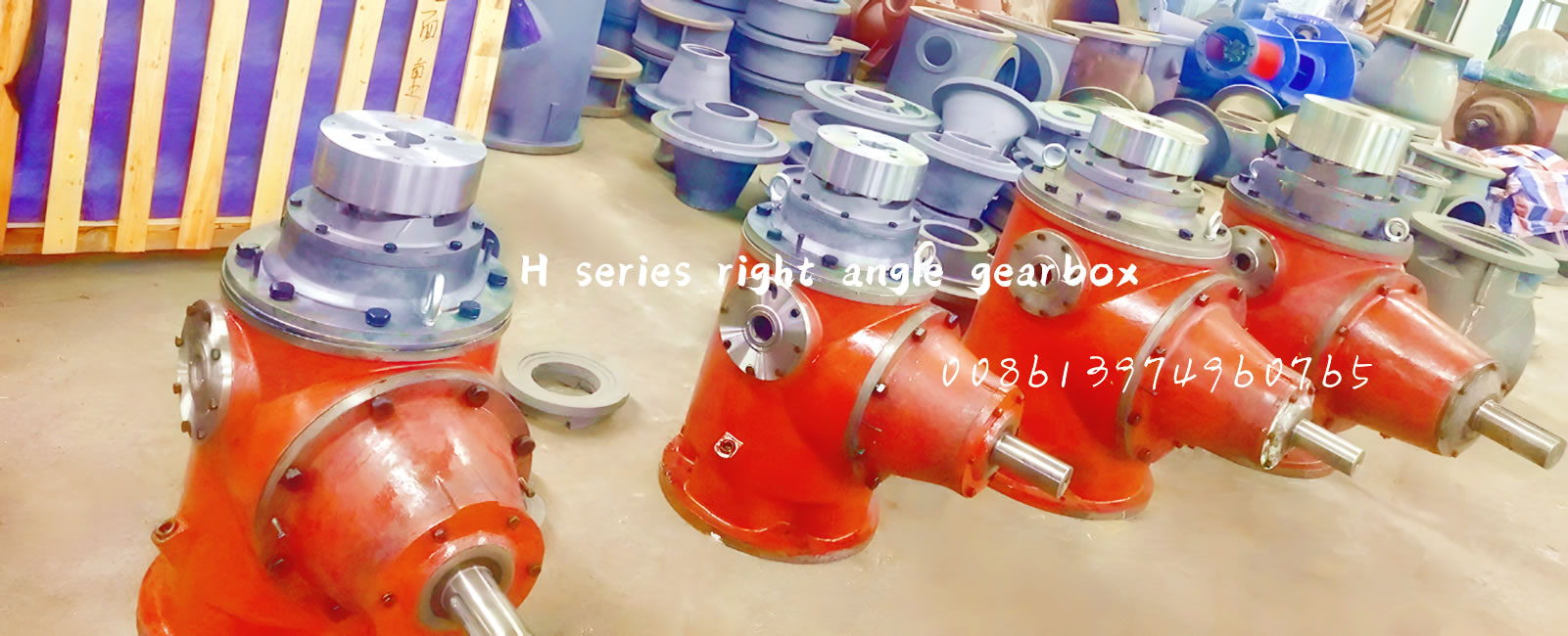
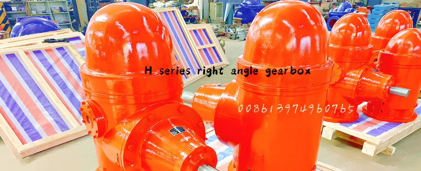
Vertical Turbine Pump | Right Angle Gearboxes
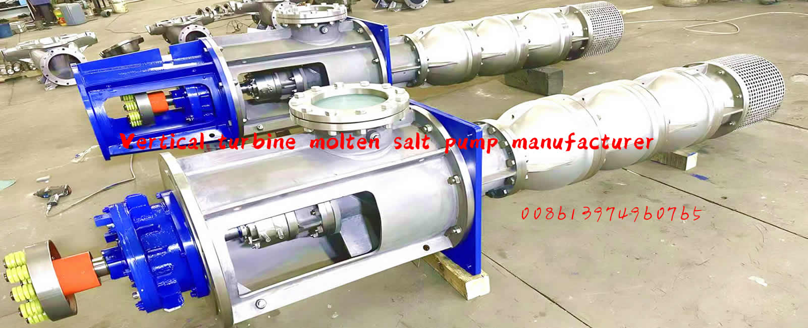
A professional manufacturer of vertical turbine pump in China
HOTLINE
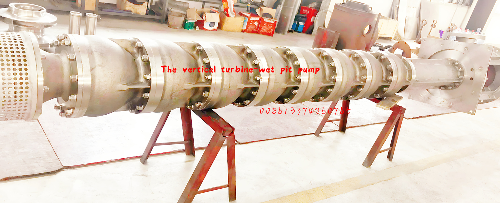
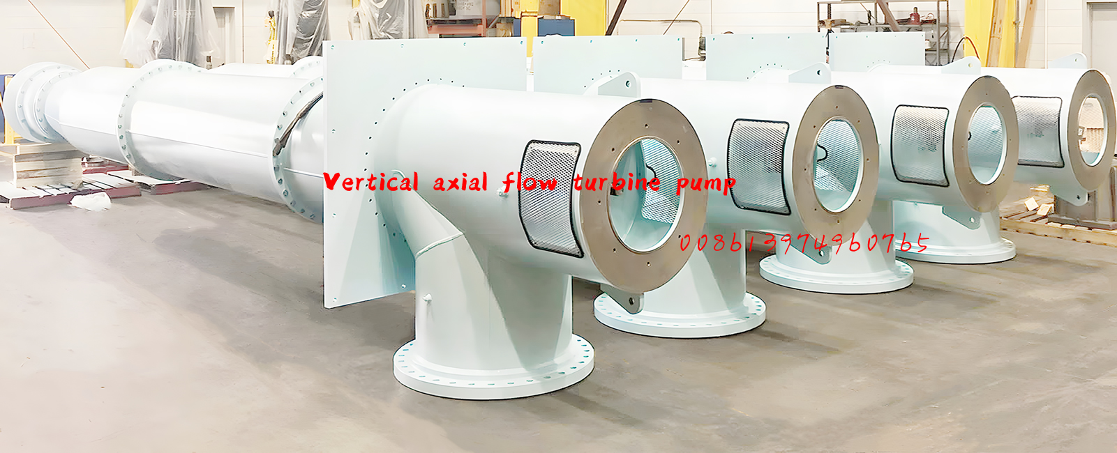
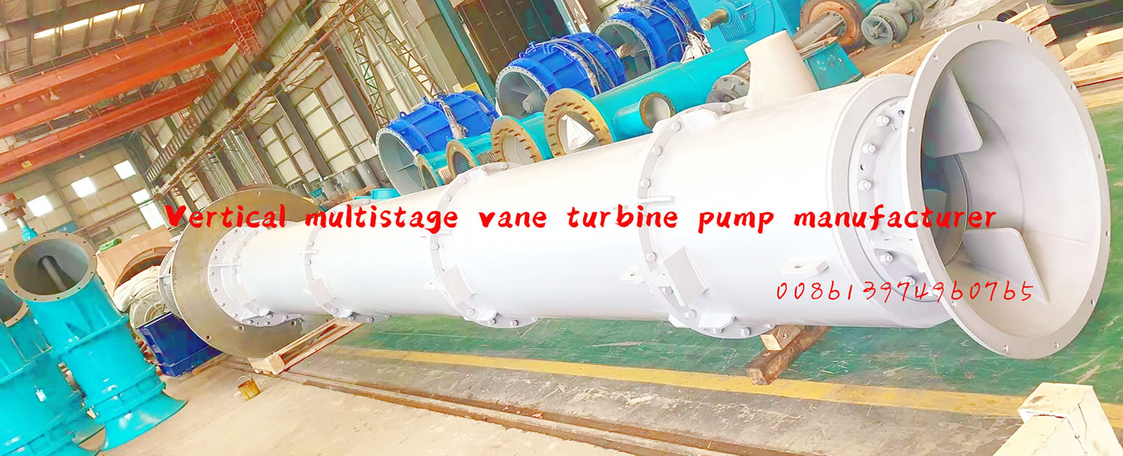
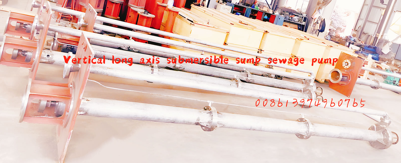
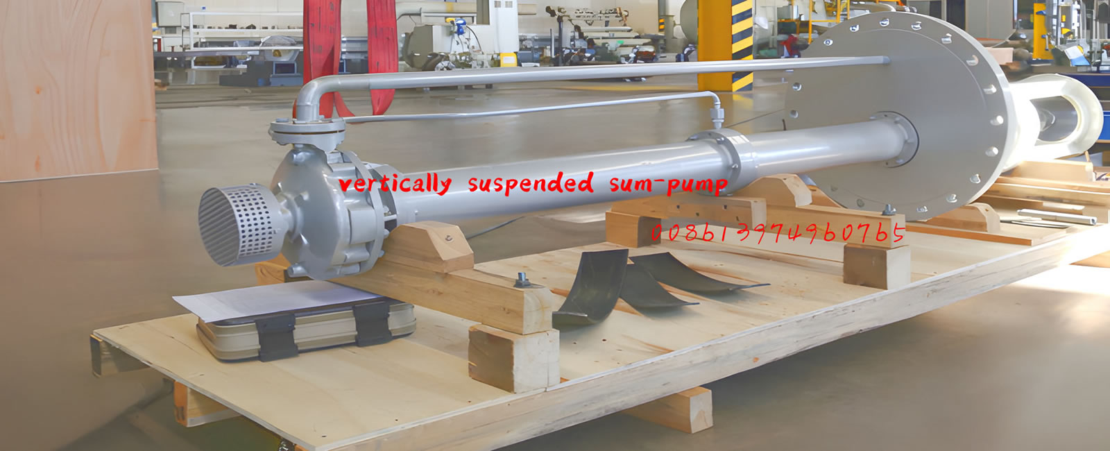
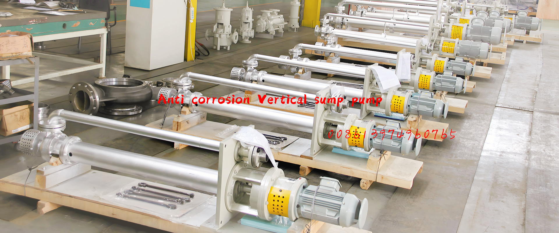
Our products: vertical turbine pump, vertical wet pit pump, vertical oil sump pump, vertical condensation pump, right Angle gearbox
A professional manufacturer of vertical turbine pump in China
HOTLINE
发布时间:2021/5/15 13:33:08
浏览次数:
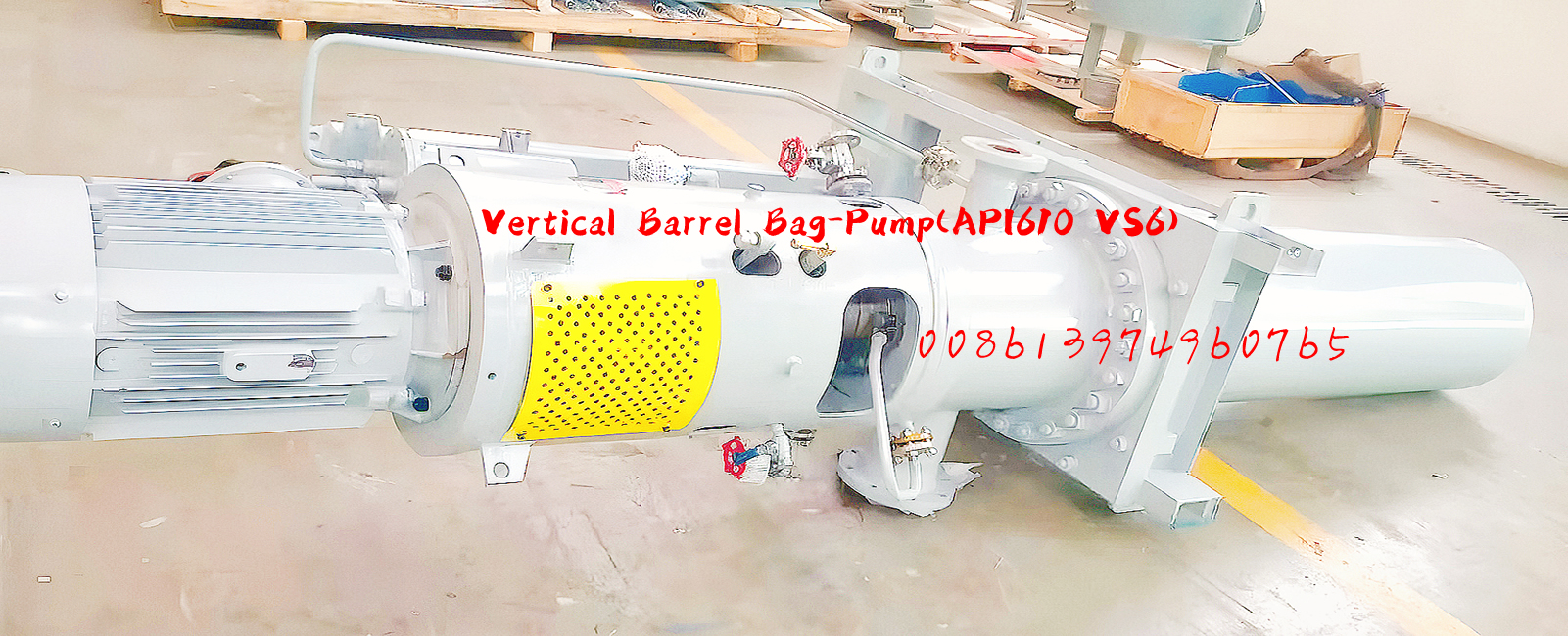
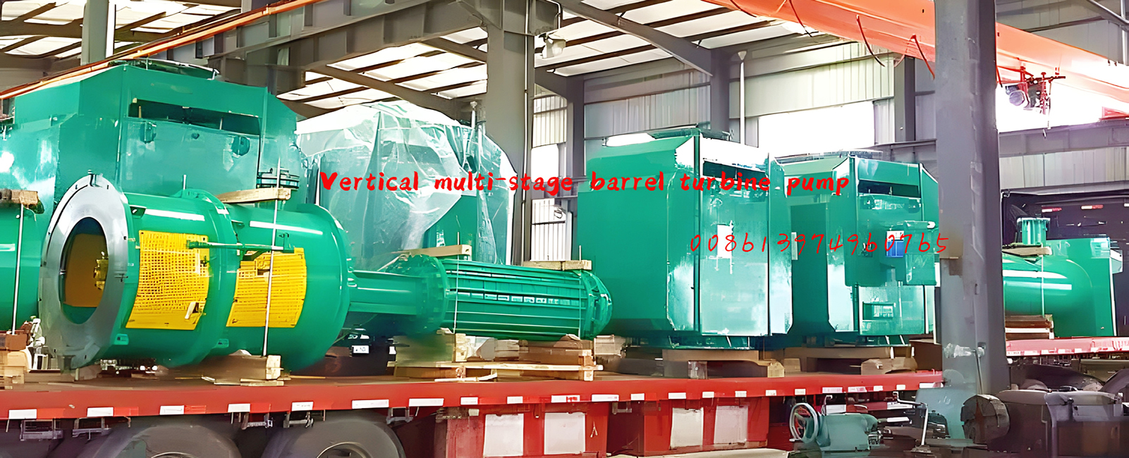
Applications Conventional Steam, Combined Cycle, Integrated Gasification Combined Cycle, Cooling Towers, General Offshore, Crude Handling and Treatment, Heavy Oil and Upgrading, Water Injection, Water Handling and Treatment, Circulating Water, Deep wells and sumps, agricultural irrigation, municipal water supply systems, water transfer, dewatering, condensate extraction, oil & gas productionGeothermal Energy.

1.Overview
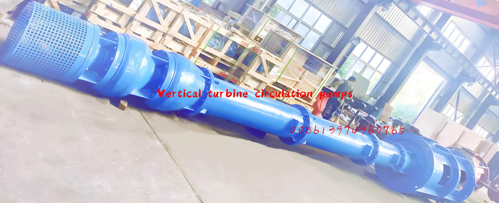
VTP is a new product produced according to the requirement of the market. It adopts the best and advanced technology in its design and manufacture. The pumps are not only reliable, high-efficient, but also easy for installation and maintenance.
The vertical turbine pump of these series are in accordance to corporation standard Q/ACXR001《Vertical long-shaft pump》.
The manual is written according to GB9969.1 < General rules for industrial product usage manual >.
2. Usage
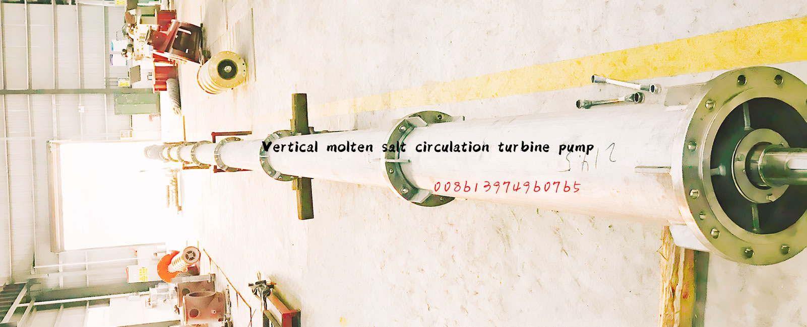
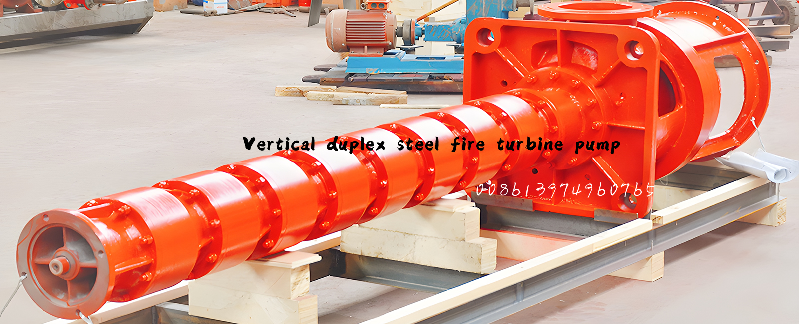
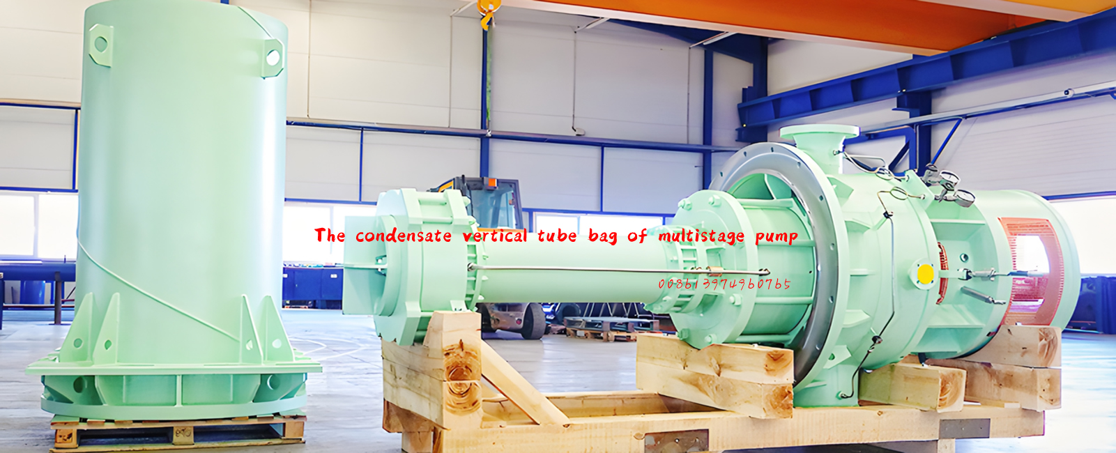
VTP is widely used for transferring those fluid with temperature below 55℃, like the clear water, rain, iron oxide skin water, sewage, corrosive industrial effluent and sea water in power stations, metallurgy industries, fire-fighting industries, mines, iron-works and public industries and so on. The transferring fluid’s temperature could also reach 90℃ through our special design.
3. working condition
Speed: 2980rpm,1480rpm,980rpm,740rpm,590rpm,490rpm,420rpm
Voltage: 380V, 6000V, 10000V
Frequency of power:50Hz or 60Hz
Capacity: 50~8400 m3/h
Head: 15~150m
Temperature: ≤ 90 ℃ ( please notify the supplier if the temperature is over 55℃)
Pumped medium: clear water, rain, iron oxide skin water, sewage, corrosive industrial effluent and sea water. Certain amount of grain is allowed like iron filings,sand and coal powder etc.
4. Nomenclature of pump models

5. Material of Main Parts

6.Structural Features
The suction inlet of VTP is straight downwards, and the outlet is horizontal. The pump and the motor could be connected directly and installed on the same foundation, or the pump could be connected to disel engine through gear box. The rotating is anti-clockwise viewed from the motor end. The main features are as below:
1.VTP is designed through the hydraulic design software. It has superior performance and its impeller and impeller body are anti-abrasive which has increased those parts’ service life. It operates steadily, safely and efficiently.
2.The strainer mesh is installed on the pump inlet. The proper sized holes on the mesh not only prevent those big impurities from going inside and causing damage, but also ensure the inflow amount and thus its high efficiency.
3. There are balancing holes on the impellers for balancing the axial force. Meanwhile, replaceable gasket rings are installed on the front and back cover which could protect the impeller and impeller body from damage.
4.The rotors include impeller, impeller shaft, middle shaft, armshaft, couplling, adjusting nut etc.
5.The middle shaft, column pipe and protective pipe could be multi-burl. The shaft is connected through screwed coupling or muff coupling. The number of the column pipes could be increased or decreased to meet the submerged depth. The impeller could be single stage or mutli-stage to meet different requirment of the head.
6.The single shaft has the proper length and its rigidity is strong enough.
7.The column pipe is connected by flanges with guide bearing in the middle. The guide bearing adopts the material of PTFE or cellon or butadiene-acrylonitrile rubber. The protective pipe is used to protect the shaft and the guide bearing. If the pumped medium is clear water, there is no need for protective pipe and the guide bearing could go without external cool lubricating water.If the pumped medium is sewage, the protective pipe needs to be installed and exterial cool lubricating water should also go to guide bearing. VTP has its self closing seal system which could prevent the sewage from going into the guide bearing after the shut-down of the pump.
8.The remaining axial force of pump and the weight of rotor parts is borne by thrust bearing in motor seat or motor with thrust bearing. The thrust bearing is lubricated by grease or oil.Pump shaft seal adopts packing seal.There is replaceable shaft sleeve in shaft seal and guide bearing to protect shaft. The axial location of the impellers are adjusted through upper parts of the thrust bearing or pump coupling, which is very convenient.
7. Structural Figure
Figure 1

Figure 2

Figure 3

8. Spectrum of VTP

9. Assembly and Disassembly
a.Preparation before assembly
1.1 Before assembly, please clean all the parts and make sure there is no missing part or faulty part.
1.2 Check the cooperating parts: include key and shaft, key and impeller, key, clasp, muff coupling and shaft, impeller, shaft sleeve, muff coupling and shaft. The radial clearance between the shaft sleeve and guide bearing is 0.15~0.25mm.
b. Parts assembly
2.1 Fix the gasket ring on the suction bell and impeller body separately with screws.
2.2 Fix guide bearing on both guide bearing body and impeller body. Install packing lining on stuffing box, don’t forget to fix key and space ring.
2.3 Installing for thrust bearing parts: Fix oil-pail in the bearing body, fix outer ring of
thrust bearing in bearing body and inner ring in rotating sleeve, then fix rotating sleeve in bearing body and finally fasten the bearing cover in the bearing body.
2.4 Middle shaft assembly: put on shaft sleeve in the middle shaft, fix retainning ring and fasten with screws.
2.5 Power drive shaft assembly: fix o-ring seal in power drive shaft, then fix stuffing shaft sleeve and retaining ring and fasten it with screws.
c. General assembly
VTP needs to be vertically assembled.
3.1 Fix shaft sleeve, key and end stage impeller in impeller shaft, then fix it in the end stage impeller bowl.
3.2 Install the retaining ring, next stage shaft sleeve, impeller bowl, key and impeller . Please repeat the above procedure until the second impeller are completely installed.
3.3 Fix retaining ring, shaft sleeve, first stage impeller bowl, first stage key, impeller,stop
Washer, locking impeller nut, suction bell and strainer mesh.
3.4 Fix key and muff coupling in middle shaft orderly, connect impeller shaft with middle shaft by half snap ring and muff coupling, fix retaining ring in slot. Fix o-ring seal in ebd stage impeller bowl, protective pipe, column pipe, guide bearing bracket with screws (with o-ring seal in bracket). Lift pump in pit and support it on baseboard of water pipe with channel steel. Then, fix each stage middle shaft, protective pipe, column pipe, guide bearing bracket, power driven shaft in order. After that, adjust protective pipe and and column pipe.
3.5 Connect discharge elbow, adjust column pipe and fix o-ring seal in stuffing box. Make the stuffing box align with the protective pipe and install it on the discharge elbow, and then fix the stuffing cover.
3.6 Fix key in power dirve shaft , install the thrust bearing parts on discharge elbow, and
then fix it with ball nuts.
3.7 Install pump coupling key and pump coupling.
3.8 Fasten motor seat on discharge elbow.
3.9 Lift the rotor by adjusting the two ball nuts of thrust bearing. The lift level is 1/2 of total beating level of the rotor, which is to ensure the smooth run during the barring.
3.10 Fix oil gauge (mark the oil-level in the oil Gauge), prepare the packing leakage pipe, connect the cooling water and lubricating water pipe for guide bearing.
3.11 If pump’s thrust force is borne by motor, there will no installation of thrust bearing parts (in the 3.6 item). Lift the rotor through the adjusting disk of pump coupling and the lift levelis 1/2 total beating level of the rotor.
Attention: 1. In the above assembly process, some small parts such as key, retaining ring and o-ring seal in the shaft sleeve could be easily lost or assembled disorderly.Thus, please pay attention to it. 2. When the pumped medium is clear water and there is no installation of cool lubricating water for guide bearing, the protective column shall not be installed. 3. If the lifting height is not enough, please hang the installed parts in the pump pit to install. Before putting them in the pump pit, fix strainer mesh and lubricating water pipe of guide bearing. |
d.Disassembly
Procedure is in the reverse order to that of assembly. Please pay attention to the following points during the process.
4.1 Please mark on the cooperating surface on the items if necessary for easy re-installation next time.
4.2 Prepare some cases for the disassembled parts to prevent them from lost and scratches. Do not mix the fasten parts, as different operational condition requires different materials.
4.3 Prepare some diluted anti-rust oil to coat those finished surface.
4.4 Below items are just for one-time use. Please prepare the spares: O-ring seal, paper washer, rust –locking parts, spring washer and the packing.
10. Installation
The installation of the pump has big influence on its running and service life. So, the installation and adjusting work should be done very carefully.
a. Foundation, Pipeline and Pump House
Professional design is recommended for the foundation, pipeline and pump house.
1.1 The foundation must be firm enough to bear the virbration of the pump and support the pump set forever. It is required that the foundation could bear the weight of 1.5 times of the pump sets. Usually, the foundation has the steel reinforeced concrete as the understructure and foundation bolts holes on it. After screwing on the foundation bolts for fixing the pump, please do another concret casting.
1.2 1.2 Donot use pump as pipe support. All pipes should be supported seperately. The pipe should be as short as possible and the number of elbow should be as less as possible in the prevention of more loss. Usually, the outlet conduit size is one standard larger than the outlet of the pump. Please install the gate valve and the check valve between the pipe and pump ( when the head is less than 20m , there should be no installation for the valves). The inner diameter of the valves should not be less than that of the pipe. The check valve is installed between the gate valve and the pump.
1.3 The pump should be installed in the proper position to allow enough space for operating, disassembling and inspection. The pump house should have good device and enough space for lifting. When the pump is driven by motor,it will be influenced by outside environment,so the house should be ventilated,It can't be too hot or too wet. When pump is used outside, please adopt the outside motor.
Attention: We will not be responsible for pump pipeline system and foundation. But we may offer some suggestion about its design and operation. |
b. Preparation before installation
2.1 Check all the equipment and make sure there is no missing part or faulty part.
2.2 Clean the foundation, the dimension of foundation bolts holes and the pump set level.
2.3 Prepare installation tool and lifting equipment.
c. Technical requirement for installation
3.1 Check and adjust concentricity of motor and the pump coupling to ensure two shafts in a direct line.
3.2 Please ensure that clearance between the pump and motor coupling meets the requirement stated in the assembly drawing.
3.3 The pipeline should have its own bracket to avoid all weight going to the pump.
3.4 After installing pipe,please adjust them again according to above procedure.
3.5 Please make sure there is no leakage between pipes and flanges.
d. Installation and Calibration
4.1 Overhang the foundation bolts through the pump seat, and then fix it with nut and gasket. Please make sure that the bolts could be hung freely in the reserved hole. Between pump seat and the foundation, please put couples of wedges. Please put gradienter on seat and adjust level with wedges ( less than 0.05mm/m). Please fix the seat on the proper height and tighten it with nuts on foundations to prevent the moving.
4.2 Use concrete to pour the seat and the hole of the foundation bolt.
4.3 After the concrete dry, please check whether there is any sign of loose of the seat and foundation bolt.
4.4 Place the pump set in the seat and prepare the cooling water pipe.
4.5 Fix the motor with coupling on the motor seat and adjust the coaxial degree of the motor and the pump by adjusting bolts.
4.6 Check the pulse of coupling. For the solid coupling, the radial pulse and end pulse of coupling of pump and motor should be less than 0.1mm. For flexible coupling, the radial deviation of pump and motor should be less than 0.1mm. And the end surface clearance should meet the requirement in the below table and the irregularity degree along circumference should be less than 0.1mm.
The outer diameter of coupling (mm) | 170 | 190 | 220 | 260 | 330 | 410 | 640 |
The radial deviation of the two coupling | 0.07 | 0.08 | 0.08 | 0.08 | 0.08 | 0.1 | 0.1 |
The end surface clearance of the two coupling | 4 | 4 | 4 | 5 | 6 | 7 | 8 |
4.7 After installing pipeline and confirming the pump rotation dierection, please check and adjust the pump concentricity again.
4.8 After the pump test-running for 2-3 hours, please do the final check again. If there is no fault, then the installation could be considered right.
Attention: 1. During installation,all the holes should be covered well to prevent dirty things from entering the pump. 2. Ensure the rotating direction of the pump: the pump is anti-clockwise viewed from the motor end. The incorrect rotating direction will cause the damage on the pump and the personal injury. |
11. Starting, Running and Stopping
a. Inspection and preparation before starting
1.1 Clean the pump and make the site clean. Please check if the foundation bolt is loose or not.
1.2 Please check if the submerged pump depth meet the requirement or not.
1.3 Please check if there is packing in the pump or not.
1.4 Check the supply of cooling water. The cooling-water should be clean soft water. The cooling water capacity for thrust bearing is 0.3~ 0.5m3/h, the pressure is 0.1~0.2Mpa. For the capacity and the lubrication pressure of the guide bearing, please refer to the appendix table.
1.5 Ensure the pump and motor to be lubricated. The oil level is up or down 2mm of the centerline of the oil-meter. Please follow the installation manual of the motor for the lubrication of the motor.
1.6 Before starting, please turn the rotor and it should be flexible.
1.7Check if the rotating direction of the motor is right: the pump is anti-clockwise viewed from the motor end.
1.8 Check if the motor, other electric equipment and instruments are normal.
b. Starting
2.1 Shut off the outlet gate valve and the pressure meter plug and open the valve of cooling water pipe.
2.2 Check the capacity and pressure of cooling water. Only when it meets the requirement, pump can be started.
2.3 When the capacity and pressure meet the requirement and the water flows more than 3 minutes, then start the motor. When the pump rotates in normal speed, open the pressure meter plug and the gate valve in the discharge pipeline gradually and adjust it to meet the requirement of needed working condition. When the gate valve on the discharge pipeline is closed, the continuous working time of the pump should not be more than 2 minutes.
2.4 Tighten the nut on the packing cover evenly to let liquid flow as drops. Please pay attention to the temperature of packing box.
Attention: 1. Under any circumstances, the pump is not allowed to run for a long time when the gate valve is closed. Otherwise, it will cause the vibration of the pump and gasification of the delivered liquid, which will damage the equipment and cause personal injury. 2. Don’t compact the packing cover too tight. Little leakage can lubricate the packing, while no leakage will burn the packing and scratch shaft sleeve. 3. When the pump deliver sewage, the guide bearing should have cooling lubricating water. If the capacity and pressure of cooling lubricating water is not enough, it will affect the pump’ s life severely. The water passing through the guide bearing should be kept for more than 3 minutes. Don’t close the cooling water until pump stops running completely. 4.When the pump deliver clear water, the guide bearing may have no cooling lubricating water, but the protective pipe should be cancelled. |
c. Running
3.1 Please check the heating of the thrust bearing which should not be over 75℃.
3.2 During the running, please keep an eye on the reading of the instrument, the temperature of the bearing, the leakage of the packing, the vibration and noise of the pump. If there is any abnormal phenomena, please deal with it in time.
3.3 Have a regular check on capacity and pressure of the lubricating water. The water must be kept running while the pump is working. And please clean the strainer mesh regularly.
3.4 The normal leakage in packing box is 20~30 drops per minute.
3.5 Please pay attention to the temperature of the bearing of the motor.
3.6 The lubricating oil level should be kept in normal range. It cannot be too high or too low. When the level is too low, please replenish it in time. Normally, replace it with new oil completely after running 300 hours for the first time. After that, please replace the oil for every 3000 hours. Users could aslo replace the oil at certain time based on the actual working condition and their experience.
Attention: 1. The pump is not allowed to run when the submerged depth is not enough to prevent NPSH from damaging the pump. 2. The continuous running is not allowed when the capacity is 30% less than that of design capacity, unless bypass pipe is added. 3. The continuous running is not allowed when the capacity is over 120% of the design capacity. Otherwise, it will cause NPSH and excessive power of the motor. 4. It is forbidden to increase the pump speed. 5.During the running, if there is abnormal noise or other troubles, please stop the machine and check it in time. |
d. Stopping
4.1 Close plug of pressure meter.
4.2 Shut off the outlet pipeline valve gradually.
4.3 Cut off electricity.
4.4 Close the cooling water after the pump stops running completely.
If the pump will not work for a long time, please disassemble and clean the pump and do the greasing and packing.
12.Maintenance and Repairing
a. Running diary and Supervise files
1.1 Running diary
The running diary must include the following item: test time, operating and stopping time, the reading of the pressure gauge, current, voltage, frequency, rotating speed, vibration, noise, environment temperature, bearing temperating, the leakage of the packig box and suction, height etc.
1.2 Supervise file
Write down the ex-factory date, manufacturer, main performance date and the inspection record of the pump, its assoicated driver ( like motor) and the gear.
b. Maintenance
Correct maintenance has a large significance to the running of the pump at its best state, the service life of the pump as well as avoiding the incident during the running.
2.1 Daily inspection item
2.1.1 Please close the plug of the pressure meter after the pump stops work.
2.1.2 Check if there is any leakage of the supply system of lubricating cool-water, pipes and pump.Please amend it in time if there is any leakage.
2.1.3 Check all instruments.
2.1.4 Keep a record of vibration value regularly and check if there is any increased noise or not.
2.1.5 Watch and check if there is any jam of the cooling lubricating pipeline.
2.1.6 Adjust the leakage amount of the packing properly.
2.1.7 Keep the pump set clean and take running records.
2.2 Monthly inspection item
2.2.1 Check the coaxial degree of the pump amd motor and adjust it if needed.
2.2.2 Check the lubricating oil and lubricating water.
2.2.3 Test vibration and noise.
2.2.4 Check if there is any large clearance between rotating fitting parts to prevent the loose.
2.2.5 If it permits, please start the machine and make it run for 5 minutes for those pumps which will not be used for a long time. If not, please turn the pump manually.
2.3 yearly insepction item
2.3.1 Check the rotating parts to see if there is any abrasion.
2.3.2 Check the clearance of impeller and gasket ring.
2.3.3 Check the NPSHr, corrosion and errosion of the impellers and its parts of the flow path.
2.3.4 Check the abrasion of the bearing and packing sleeve.
c. Repair
The pump should be disassembled and repaired when necessary ( for example, the vibration, noise and the bearing temperature is over the specification, and the capacity and head is decreased obviously). For those pump in continuous working state, please check it at certain time of the year..
3.1 Write down the details of each repairing work for the next reference.
3.2 Prepare the spare parts. During purchasing, write down the name, material, quantity of the spare parts. Besides, please keep a record of the pump model, name, ex-factory date and the manfacturing no..
3.3 The disassembly is in the reverse order to assembly. After disassembly, please get rid of the rust and daub it again.
3.4 Check the clearance between the impeller and seal ring. Please refere to below chart.
Norminal diameter | ~125 | ~160 | ~200 | ~250 | ~315 | ~400 | ~500 | ~630 |
The maximum clearance allowed |
1.1~1.8 |
1.2~2.0 |
1.3~ 2.2 |
1.5~ 2.5 |
1.7~ 2.8 |
1.9~ 3.1 |
2.1~ 3.5 |
2.4~ 4.0 |
3.5 Check the abrasion of guide bearing. Please see below table for reference.
Nominal diameter | ~60 | ~80 | ~100 | ~120 | ~140 | ~160 | ~180 |
The maximum clearance allowed |
0.4~0.8 |
0.5~0.9 |
0.6~1.0 |
0.7~1.2 |
0.8~1.3 |
0.9~1.4 |
1.0~1.5 |
3.6 Check the abrasion of the shaft sleeve and the packing sleeve. If the abrased slot’s diameter reaches 1~2mm, please replace it.
3.7 Check the abrasion of the impeller and impeller body.
3.8 Replace the sealing parts , like packing seal, O-ring seal and paper washer.
3.9 Assemble the pump in order and rotate the pump rotors which should run smoothly.
Attention: The safety procedure and regulations should be followed throughout the inspection. Before any inspection, please do as below: 1.Cut the motor power off and all the instruments. 2.Shut the outlet and inlet valve. 3. Cut off cooling water. |
13.Trouble Shooting
Problems | Cause of problems | Solutions |
The pump wouldnot start | 1. The fault of motor or electricity-supply power. 2. There is foreign objects in the rotor parts. 3. The bearing is clogged. 4. Insufficient startup condition.
| 1.Repair the motor or electricity-supply power. 2.Clean the rotor parts. 3.Clean or change the bearing. 4. Check what is the problem and make it meet the startup requirement. |
No fluid out or the flow rate is not enough | 1.Sundries in the suction case, discharge head and impellers. 2. The gasket ring is seriously worn or the impeller is damaged. 3. Incorrect rotating direction. 4.The rotating speed is too low. 5.The submerged depth is not enough and there is air-in. | 1.Clean filter, impeller, guide impeller body, discharge pipe and valves. 2. Replace the damaged parts. 3.Make the direction correct. 4.Test the voltage and frequency and check the motor. 5. Increase the suction height.
|
Overload of the pump power | 1.The bearing is damaged ( including the guide bearing) 2. Foreign objects in the pump. 3. Friction between the impeller and gasket ring. 4. The packing is too tight. 5. The rotating is too fast. 6. The capacity is over specification. 7. Only single-phase electric wire is working. | 1. Replace the bearing. 2. Get rid of the foreign objects. 3. Adjust the clearance. 4.Loosen the packing. 5.Test the voltage, frequency and motor and make it correct. 6. Reduce the discharge valve. 7. Ask professionals to check and repair it. |
Abnormal vibration and noise | 1. The submerged depth is not enough and there is NPSH in the pump. 2. The impeller is unbalanced. 3. The shafts are not concentric or got bent already. 4. The foundation bolts are loose. 5. The bearing is damaged. 6.The abrasion of the guide bearing and shaft sleeve cause the increased clearance. 7. The trouble in the discharge pipe.
| 1. Increase the absorption height and reduce the discharge gate valve. 2. Adjust the balance of the impellers. 3. Adjust the concentricity and straighten the shaft. 4.Tighten the foundation bolts. 5. Replace the bearing. 6. Replace the guide bearing and shaft sleeve. 7. Check the discharge pipe and get rid of the trouble. |
Overheated bearing | 1. The pump shaft and the motor shaft is misalign. And the pump shaft is inclined. 2. the damaged bearing. 3. There is no oil in the bearing. | 1.Check and adjust the radial flop. 2.Replace the bearing. 3. Fill the lubricating oil. |
14. Packing, Transportation and Storage
a. The bare packing is adopted normally.
b. Release the water in the pump before the packing.
c. According to the technical requirement of the packing, the pump should be fixed firmly on wood in the box bottom to prevent it from reverse and damage. The rotor also needs to be fixed to prevent it from damaging the bearing during the transportation.
d. Add the flange cover on the inlet and outlet cover to prevent the foreign objects from going inside the pump.
e. The technical data should be put into the water-proof and moisture-proof plastic bag and then put into the packing case.
f. Bump and Inversion should be avoided during the transportation.
g. When the pump arrives the site, the user should open the packing case to see if there is any part missing, abrasive or damaged.
h. After the case is opened and if the pump will not be put into use for some time, please get rid of dirty oil and rust, and then coat the pump with grease.
i. For storage, please pay attention that it may get rusted or damaged. The period of validity of oil-sealing is 12 months and it should be coated after 12 months. The bearing should be cleaned if the pump is going to be used more than 6 months later after the ex-factory date.
Attention: We could make the special pump according to the customer provided performance specification.
TEL:+8618507312158
QQ:461710166
Email:sale@ljpump.net


WeChat number:ljpump666
Copyright © 2002-2022 Vertical turbine pump factory in hunan province set machinery manufacturing co., LTD Vertical turbine pump
Copyright © 2002-2022 Hunan machinery manufacturing co., LTD. All Rights Reserved.
+8618507312158
WeChat Qr Code